GBC Competition Carbon Data Case Study
GBE > Encyclopaedia > Files > Calculators > Whole Building Calculators > Case Study > G#38491
GBC Competition Carbon Data Case Study
About:

Architectural Competition Entry
Design Review and Carbon Data
- Metsa Timber Technology Competition 2020 Entry
- GBE was approached by exStudent Samael Coco from LSBU Post Graduate Architecture EREID Module
- 2 of GBC’s component parts were developed at the time of the EREID course
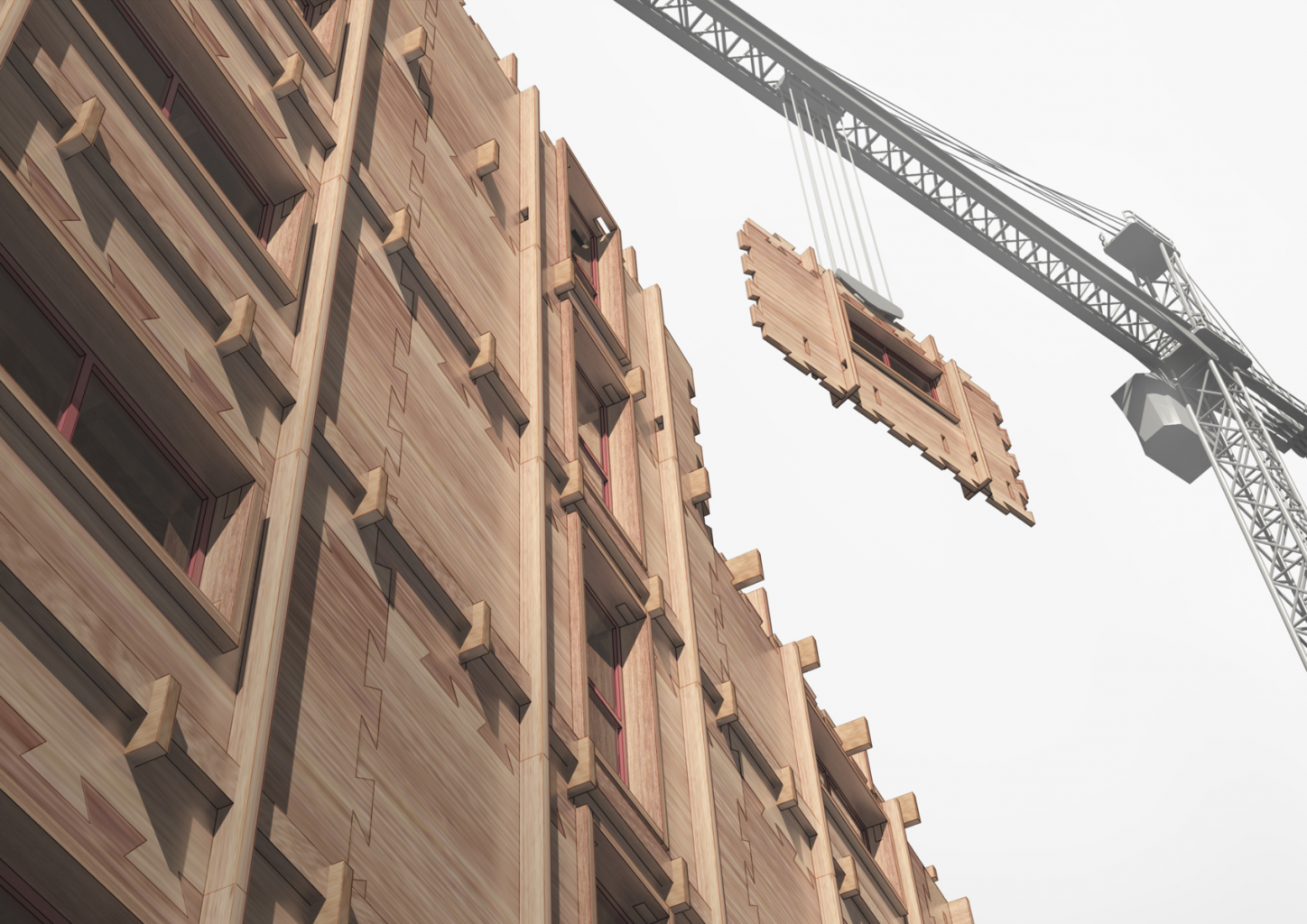
- Samael’s competition entry proposed a replacement for a 1960’s tower block load-bearing precast concrete facade with a load-bearing solid wood panel of Kerto LVL Laminated Veneer Lumber with jigsaw inter-connecting edges connected to an interlocking solid timber super-structure
- GBC carried out a critique of the proposal to help in its development and refinement
- See Schedule below
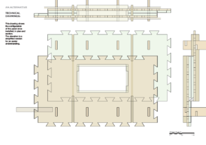
- Samael prepared drawings and a report and investigated alternative insulation materials
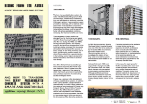
- Samael Coco presentation Rising From Aches Rev2 PDF
- GBC prepared and provided:
- U value calculations for before and after with each insulation option
- Comparisons with Regulations, AECB Carbon lite, Passivhaus & LETI U values
- Embodied Energy, Embodied Carbon and Sequestered carbon before and after calculations

Elemental U values and comparisons
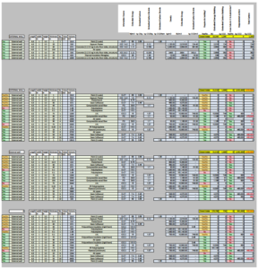
Elemental Embodied Energy, Embodied Carbon and Sequestered Carbon
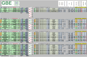
Combined together
Crane lifting panel to install
28th May 2020
© GBE GBC GBL NGS ASWS Brian Murphy aka BrianSpecMan **
3rd November 2020
GBC Competition Carbon Data Case Study
See Also:
GBE Satellite Website
- https://GreenBuildingCalculator.uk
- Home
- Awards (Scroll down)
- Q&A
- Bespoke
- Buy-now
- Contact Us
GBC Green Building Calculator
- GBC Green Building (Calculator) G#38491
- GBC About (Calculator) G#38802
- GBC ScreenShots (Calculator) G#38796
- GBC Development Versions (Calculator) G#38792
- GBC Features Benefits (Calculator) G#38788
GBC Case Study
- GBC Competition Carbon Data (Case Study) G#38838 (this page)
GBE Collaborate Service
- CPD Events (Zoom/Teams)
- Introduction to GBC V1.0.0. and V20 ambitions
- Competition Entries
- GBC Design Review
- GBC Questions and Answers
- GBC Carbon Data
- Building Type Analysis
- Element Analysis
- Development of Bespoke requirements within or without GBC
GBC Building Type Analysis
- Developer EcoHouse Type being considered
GBC Bespoke Developments
- Cost and Carbon effective Window Upgrades being considered
GBE CPD
- GBC CPD Green Building Calculator PDF Show
- GBC CPD Green Building Calculator V1+ STBA 061020 S87 PDF
GBE Past Event
- SPAB STBA Conference 2020 (Event) G#38634
GBE Shop
- GBE Green Building Calculator Big Practice (Shop) G#38525
- GBE Green Building Calculator Small Practice (Shop) G#38524
- GBE Green Building Calculator Student (Shop) G#38520
GBE Video
GBE Projects
- CAP’EM and CAP’EM Compass
- Interreg funded project to develop an LCA & EPD method and Tools,
- https://greenbuildingencyclopaedia.uk/?p=546
GBE Calculator
Psi calculation
WasteCost® Lite
- GBE Waste Cost lite calculator
- https://greenbuildingencyclopaedia.uk/?p=531
Whole Building Calculators
- GBE shop
- https://greenbuildingencyclopaedia.uk/?p=11095
- It proved challenging for the students but they persevered and succeeded.
- GBE Embodied Energy, Embodied Carbon and Sequestered Carbon Calculator (EE EC SC)
GreenGauge Advanced Details
- (Thermal bridge & Psi values)
- https://greenbuildingencyclopaedia.uk/?p=25033
GBE Datasets
- ICE for (EE EC SC Database v3) (currently using 1.6)
- ICE Database (Jargon Buster) G#1018 N#1037
Thermal Mass Calculator
LCA and EPD datasets
Decrement Delay
- (overheating prevention)
- https://greenbuildingencyclopaedia.uk/?p=31148
Condensation Check
© GBE GBC GBL NGS ASWS Brian Murphy aka BrianSpecMan **
31st October 2020 – 3rd November 2020
GBC Competition Carbon Data Case Study
GBC Design Review
GBC Questions and Answers
re. Samael Coco’s Metsa Competition Entry
|
Question or comment |
Response |
|
Page 1 Some of the problems with precast concrete towers were: |
The government promised to built tons of houses on a shot time so everybody was hurrying up to do so. |
|
lack of skills (and training?) for a totally new method of construction |
The panels were built poorly in the first place. |
|
Unskilled labour brought to site to save money |
Technically didn’t required skilled labor. |
|
Unfamiliar details |
TRUE |
|
Complicated details that were easily done inadequately leading to structural weakness leading to Ronan Point progressive collapse |
I guess that the engineer did not think about a possible failure of a panel with following the collapse of an entire section of the building. |
|
Inadequate thermal insulation |
TRUE |
|
Bad thermal bridging |
Having overall low performances the thermal bridge is not a big concern, at least, it wasn’t back then. |
|
Interstitial condensation corroding reinforcement |
Due to gaps between the panels. |
|
Surface condensation leading to mould and asthma |
TRUE |
|
Page 2 Enough information to do a rough U value |
Do you refer to the original concrete construction? Do not have more information about it. I have enough no need for more |
|
Enough information to do a rough Thermal bridge calculation |
Same as above. |
|
Enough information for a rough Embodied Energy and Embodied Carbon calculation |
I guess we can do an estimate. |
|
Define LVL at its first use |
It is a structural load-bearing wall which it will be used for all the elements of the project. What you mean by define it? LVL = Laminated Veneer Lumber |
|
Reread your sentence and add missing words and singular to plural |
I know, I did a check spelling but considering that English is not my first language I’m sure there are still plenty of little mistake, I’ll try to spot them! |
|
The diagram needs to align with the text that describes it |
OK, I’ll move the text above the diagram |
|
Use red text and red diagram? |
Yes, good idea. |
|
But you only show external façade internal partition and floor application in following pages, no Core walls |
I thought that the internal partition and the core were made in the same way. Would it work? Partition sits ON floor not on edge of it may have acoustic and fire performances Core wall is like external elevation but must also be fire resistant |
|
Page 3 The obvious issue is how do the offset edges of two units on two adjoining floors, above and below each other meet and join? You have not drawn it in any other drawing. |
I have added a drawing, I supposes that will address this issue. |
|
The next issue is the offset horizontally how do they meet an internal or external corner and all larger openings? Page 6 corner detail does not show it in the context of a wall with two adjacent panels attached. |
I have added another drawing showing the external angle detail connected to other panels. I haven’t worked on internal partition, I guess that because they are not structural they can be added at the end as finishes, so not really part of the project. Open plan needs to address all of its components, acoustic or visual privacy is an essential part of housing or office planning. |
|
Page 4 What are the two window sill and head heights above the floor? Are they both acceptable? |
Yes, they are about right. Put the dimensions on the drawings so all can see. No surprises. |
|
How does a Door opening work? |
I haven’t designed the door and windows, maybe I should. I did this way because I wanted to give that feeling of different possibilities, so the same system can look very different – which is an important part. We don’t want to say this is it and it will look the same all over the world. Not what does a door look like, how does a door opening work in your system |
|
Page 5 End of floor beams is a vulnerable to failure by shearing off. |
Yea I know it’s a weak point, any suggestion? Cross laminated timber or embedded flitch plate |
|
Page 6 Show the walls either side of the corner |
Drawing added! |
|
Show a core with 4 corners and 4 panels to show the layout. Does the directions of the offsets change with each floor level or consistent? |
Drawing added! The offset is consistent. |
|
Page 7 Notches in timber reduce the strength of the section to the depth of the remaining un-notched section A has no shear strength at its most vulnerable point the end bearing A2 is effectively half the depth only B has no shear strength at the bearing and no strength at mid span The grid may offer some strength but it will need to be glued or screwed in a most competent way, with curing time, that is unlikely on site. |
I thought that when they would combine together they would get some strength back, but you’re right, it would require the precision of a goldsmith. Also being one up and one down, as a basket, I thought it would increase the strength in case on a collapse of a panel. What do you suggest then? I can just take the page off and we focus on the panel. You cannot look at half a system or ignore a problem There are screw manufacturers who could develop a bespoke screw to fix this Make a call to HECO, APTUS or ROTHOBLAAS Screws with two lots of opposing threads at each end of shaft that pull parts together can increase shear strength. Diagonally through a joint or diagonally across a gap. |
|
What is the sequence of assembly? Or do the floors carry the panels? The floors need to be assembled and then fed into the panel holes. Panels going around a corner cannot rely on being able to be fed onto the floor beams. |
It starts form the angles (as it would be impossible to slide the angles in) then the panels and finally the beams and the additional beam to secure the structure in place. Corners not angles The beams are assembled on site. I might try to make a drawing explaining it. Thumbnail sketches of assembly sequence will be a great addition to the submission, but do it at a corner so you know all the issues. consider two floors so you know the whole picture. The panels carry the floor, but the floor beams would also support the panel in case of a failure. Lest see them in the sequence of assembly |
|
Page 8 Concrete Code of Practice tolerances +/- 20 to +/- 40 mm and timber tolerances +/- 3 mm are at odds to each other. |
I am aware of the need of tolerance but I haven’t shown any. I can state it in words. You need to show the interface and how it is resolved |
|
Page 8 So how do you set the first corners and panels to allow the first lift to be accurate enough for following units to be assembled on top and for dovetails to meet and interlock. |
Good question, I guess that the concrete base has to be accurate enough to enable a precise assemblage. In construction screeds level floors and mortar beds level walls. Wall plates set level line for roof trusses and they are anchored down. You need to have a solution and draw it. |
|
You need to draw the first starter unit and the last topping unit to show how it works |
I’ll try to do more drawings showing the construction process. |
|
Manufacturing tolerances will make one sets of the dovetails easy to assembly in the factory, getting two sets to align will be more challenging. |
It’s the same panel, just rotated, so I guess it would be not that hard, or not? two panels offset in two directions, rotated and spaced apart and dovetailed connections, with accurate fit makes a difficult assembly. Inaccurate fit makes a leaky assembly. |
|
But on site with a bit of tilt from the strops and craning, a bit of wind and a bit of wet will make assembly of two sets of dovetails difficult if not impossible. |
TRUE |
|
Blokes with mallets will be there knocking hell out of the dovetails trying to get them to assemble |
TRUE |
|
LVL by virtue of the laminations has weak planes so mallet assembly will risk dovetail loss |
|
|
If you add assembly tolerances to the dovetails the gaps need to be made airtight. |
I thought that backer rods work both for air-tightness and autistic break. Acoustic Backer rod is usually behind sealant Rubber sealing rod might be better name How do you get them in and to stay there without being rolled out by the dovetails? You add shallow grooves to the dovetails surfaces, and insert the seals into the grooves Then assemble. But two hours of labour intensive and inaccurate work on site to install the seals. It will be worse than the concrete panel fiasco. You could add an expanding foam strip in the groove example Iso-Chemie but you have a 3 hour window between application and full expansion, not enough time. You will need to consider air tight sealing tape over the joints, labour intensive and fiddly work. |
|
You are pushing the assembly into the realms of the Ronan Point territory but replacing structural failure with airtightness failure |
|
|
If you were to subject this system to a gas explosion the upstanding ends of the beams will shear off and the dovetails will side outwards and panels may fall to the ground. |
I thought that the outer horizontal beam would secure the panels form sliding in and out. But if they have sheared off, nothing to stop them |
|
If the dovetails are a tight friction assembly the adjacent 4 panels above, below and beside may all move outwards and potentially fall, this may initiate a limited displacement |
|
|
Progressive collapse is less likely than Ronan Point due to the interlocking of the remaining panels around the openings |
|
|
Weather you add cladding or not the wind pressure and internal wind pressure buffeting could progressively push or pull the panels in or outwards and potentially displace a unit |
I thought that the outer and inner horizontal beam would secure the panels form sliding in and out. As long as the beam ends have not sheared off during assembly |
|
Show how cladding fixing forces are received and distributed by your panels |
Depends on the type of cladding, it would have some brackets attached to the panels. Show a cladding solution in full |
|
Is a 200 mm gap enough for a timber/plant based vapour open construction? |
Honestly, no idea. Unlikely |
|
200 mm you may be forced into plastic insulation |
Multilayered natural insulation wold not work? Unlikely |
|
You need to consider the size of insulation boards 900 x 450 mm normal for masonry. What other sizes available? How well do they map onto Page 9 How much cutting and waste and consequent air leakiness How fixed? |
The insulation is cut following the jigsawed edges and the ‘waste’ from one panel is attache to the next one, no? Ignoring the jigsaw edges, cutting around floor beams and openings will be wasteful Not sure about specs and materials. |
|
I will do a U value check |
Thanks |
|
What energy performance target is set by the brief? |
I’ll attach a screen shot of what we can submit, no target required. Cannot provide fire performance I do not think it exists Not sure if acoustic info is easy to get either |
|
B Regs Part L? Passivhaus? LETI? Other? |
|
|
Page 9 What is the height of the floor beam holes? And the two interlock slots? |
Added! |
|
Page 11 Consider realigning the Legend and the key numbers to read with the dimensions, so you read the whole drawing on its side This is not a plan Use line weight to distinguish section from view |
It’s seen from above, so I called it plan, but can take it off. I read this a a vertical section my mistake, it is a plan Line weight would help, that’s true. Please do |
|
2 and 10 cannot cross the cavity if 12 in masonry |
It would have an additional 75 mm gap. Not as I read the drawing it touches the inner face of the cladding zone |
|
3 opening frame is what |
It’s the window frame, how can I make it cleared? What is it made of? Add a nominal windows? Shall I simply say LVL window frame? |
|
12 you need to show at least one complete external finish Currently this is not adequately supported by your panels |
That would be good, I’ll see what I can do. Timber weatherboarding, underlay, battens and cross battens, but what is it attached to? and how is to attached to your system? |
|
4 + 4 what materials are you considering? 180 mm will force you to use plastic insulation |
It’s indicative, it could vary, I thought that 180 mm would be enough… apparently not. The purpose of the calculators was to get students understanding the thickness of insulation necessary to insulate buildings to today’s and tomorrow’s demands. |
|
5 is a cavity for heat to dissipate into |
At the bottom into the weep holes, no? we do not want cavities in construction for heat to dissipate into. Brickwork has cavities to allow ventilation and moisture out. |
|
7 will need to be minimum 50 mm thick as a fire break |
OK I’ll change it. |
|
8 No idea how that works |
Me nether to be fair, shall I change it in a 50mm wood closer? 6 mm mild steel is a fire barrier, but draw something you understand. |
|
11 backer rod does what? Is it weather tight seal? Or backing to sealant |
It is the weather sealant, closing the tolerance gap and hopefully giving some acoustic break. See my previous notes |
|
Page 12 Suggest you show this assembly of two panels interlocking to see what gaps need resolving |
Ok I’ll as page 13. |
|
6 this is not a masonry cavity wall where will the weep hole tray drip to? |
On the outer side of the panel? Is that not correct or perhaps just not clear enough? Close the 20 mm cavity by using 200 mm insulation No moisture should occur in this so no need for weep holes and drainage |
|
9 panel secure beam may make assembly on site impossible or break the beam end off |
Yea, 75mm is not much, but I didn’t want to have the beams sticking out too much. Any alternative? CLT or metal flitch plate embedded, or metal fixing? They also need to connect with and support the external cladding, you ned to work that out. |
|
Page 13 When will the services get installed in the sequence of assembly? |
I guess during the assemblage, as soon as one panel is placed, before placing the one above. Needs co-ordination of trades to be on site at same time. Or long delays between one lift at a time. First fix would normally occur once enclosure is in place. This needs service trades to be installing during wall assembly, at big Health & Safety risk. |
|
I will do U values and EE EC SC calculations Friday afternoon. |
Great |
|
© GBE NGS ASWS BrianMurphy aka BrianSpecMan 28/05/2020 |
29/05/2020 |
Thank you very much.
© GBE GBC GBL NGS ASWS Brian Murphy aka BrianSpecMan **
3rd November 2020